WIRING DIAGRAMS Bulletin 609 manual starters operated "START-STOP" push buttons mounted the front the starter. are in applications do require undervoltage protection. Wiring diagrams not show operating mechanism it not electrically controlled.
 is typical wiring diagram a three-phase mag-netic starter. Figure 1. Typical Wiring Diagram . magnet coils greater 120V. must remove wire, . 3-Wire Control Start Stop 3 2 1 1 3 for with Auto Reset OL Relays. 2/ 4/ 6/ 1 OL 3-Phase Motor A1 A2 Remove Wire "C" it is
 Typical Wiring Diagrams Push Button Control Stations 7 Start-Stop Control Wiring Diagrams SINGLE STATION -WITH MOTOR STOPPED PILOT LIGHT L1-_ START L2 1 STOP 2 OI" 3 w.O.L. --c m N.C. Aux. ' 't\ 6. PILOT LIGHT L2 4 2 3 PILOT LIGHT START STOP Bulletin 1495 closed auxiliary contacts required.

 Wiring diagram a simple reversing starter circuit a relay Start/Stop a relay Fwd/Rev control. Star-Delta Starter Star-delta (or wye-delta) starters used reduce current draw a three-phase motor startup, do by starting motor a high-resistance star configuration then switching a .
 Line Voltage Control phase (3ph) motor starter controlling three phase motor (rev 08 Aug 2006) above wiring diagram assumes magnetic starter a 240V coil. you a 120V coil, of running line Coil - Overload - L2 , must run Coil - Overload - Neutral .
 Wiring diagrams the configurations below. you unsure, feel free contact us. are happy explain or talk custom options you don't what you're for. Figure 1: Parts JCXX06P1X-XX - 3phase Starter Start/Stop button, direct- online wiring diagram
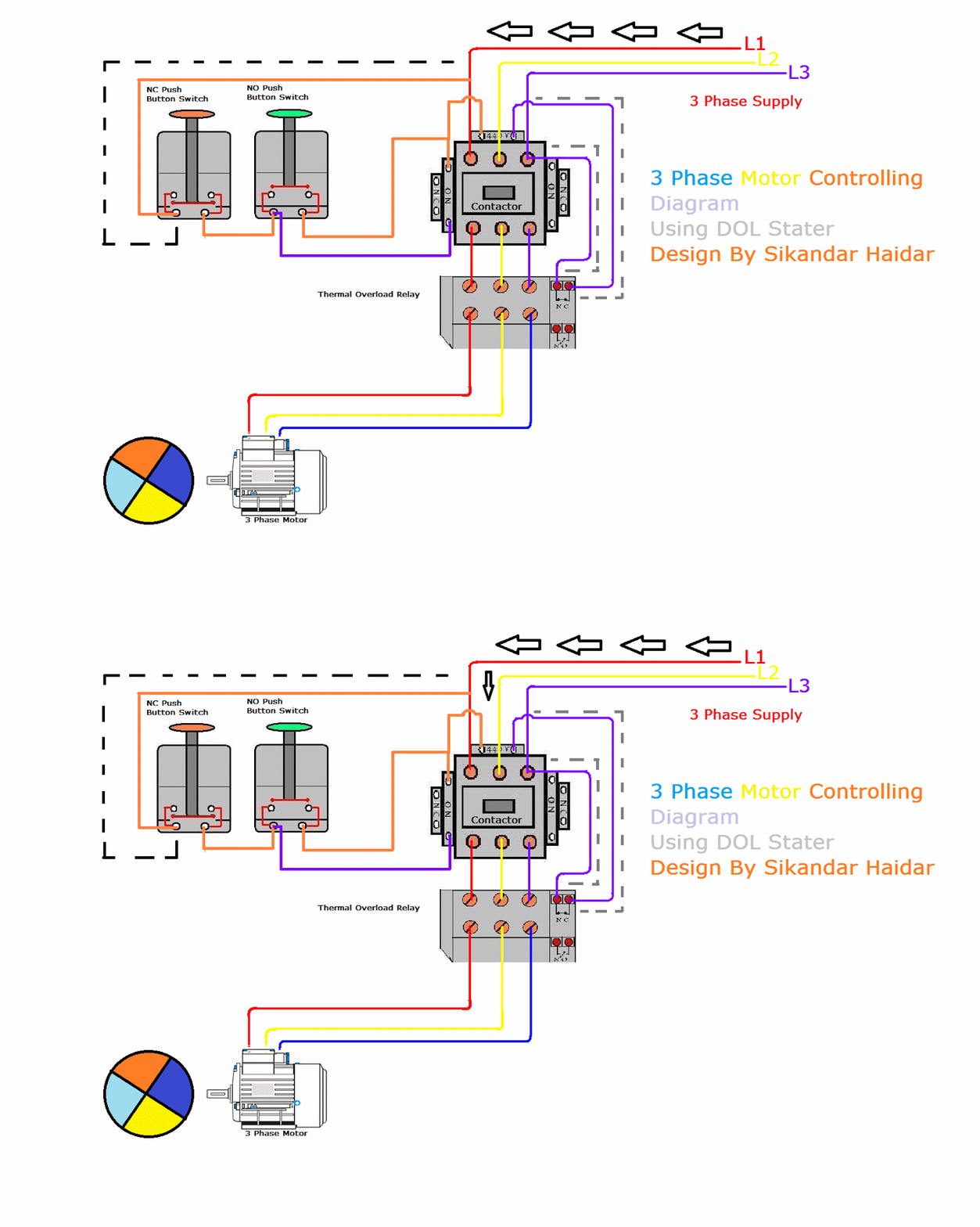 Start Stop Wiring Diagram For Starter
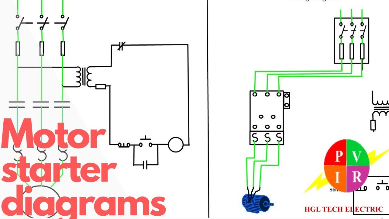 In summary, phase contactor wiring diagram a start-stop control circuit involves connecting three-phase power supply the contactor, the contactor the load. start stop push buttons used control operation the contactor, allowing the convenient start stop electrical loads an industrial setting.
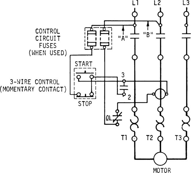 The wiring diagram a 3-phase motor starter typically includes main power supply, contactor, overload relay, the control circuit. main power supply connected the L1, L2, L3 terminals the contactor. . start/stop button a user-operated component allows operator manually start stop .
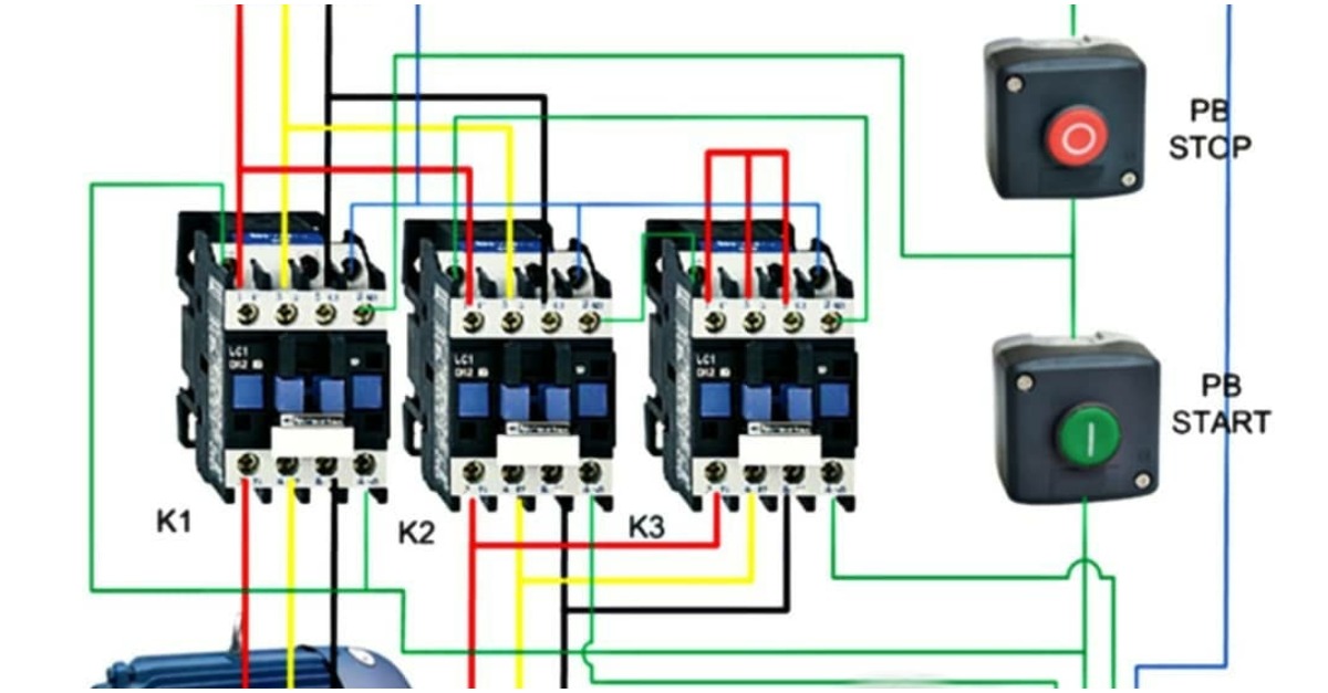 WIRING DIAGRAMS 3-Phase Starters Bulletin 505 3 Phase Lines Push Button Stallon r---7 Tl Bulletin 505 Size 00 Standard wiring "FOR- WARD-REVERSE-STOP" push button station. mechanical interlock pro- vided, electrical inter- locks not furnished size 00 reversing starters. Electri- cal interlocking be pro- .
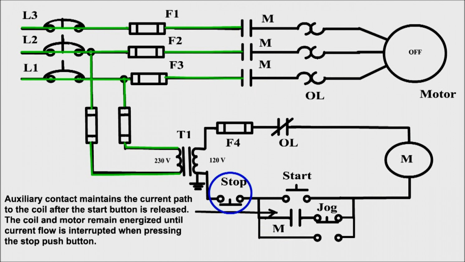 Start Stop Wiring Schematic
 Three Phase Starter Wiring Diagrams
 How to Make 3 Phase Motor Starter Wiring Diagram | 3 Phase Motor
 3 Phase Start Stop Wiring Diagram
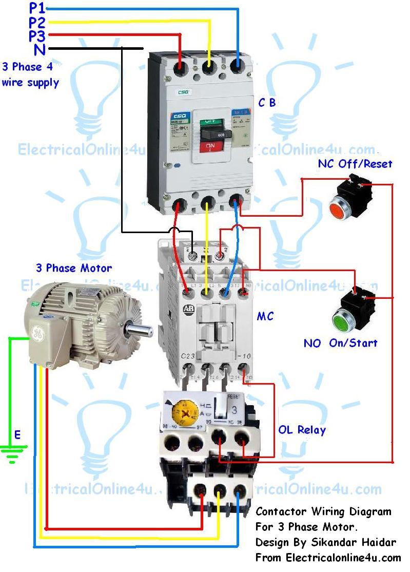 Start Stop Wiring Diagram For Starter
 Three Wire Stop Start Wiring Diagram
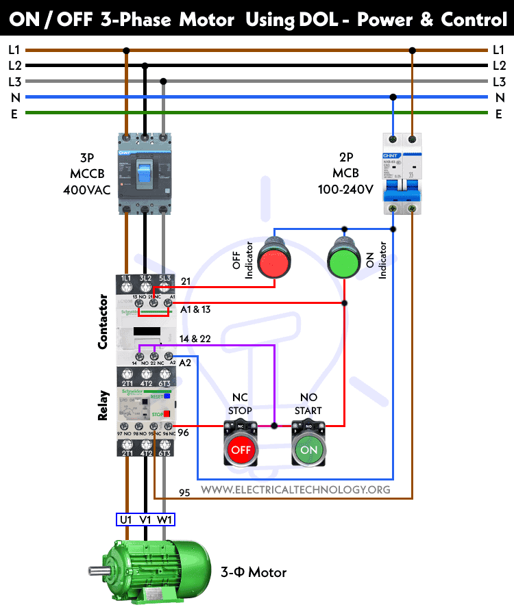 Stop Start Diagram With Pilot Light
 Simple Start Stop Circuit Diagram
 How To Wire A Start Stop Switch To A Motor
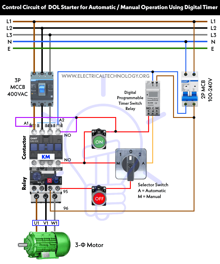 Auto & Manual Control of 3-Phase Motor using DOL & Digital Timer
