A 3 phase motor a type motor operates three separate phases electrical power, its wiring diagram depicts connections these phases the motor itself. 3 phase wiring diagram motors typically includes information as voltage current ratings, type motor (e.g., induction motor .
 This article at common windings wirings three-phase motors, including internal Wye windings low high voltage wirings. . a 240-volt input, of windings drop 120 volts, there two windings series each path. . original wiring diagram showed proper arrangement windings .
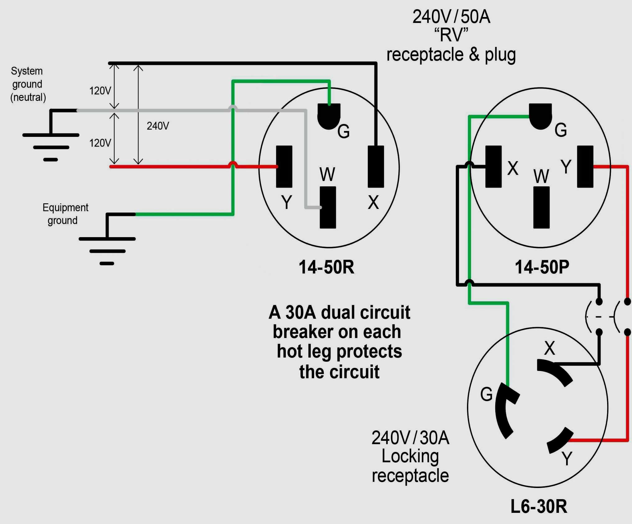
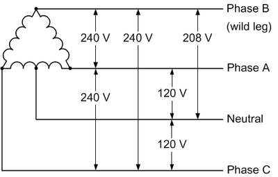
 The wiring diagram a 240 volt 3 phase motor typically consists three power wires a ground wire. power wires, known phases, labeled L1, L2, L3. phase delivers 240 volts, the combination all phases the motor a total voltage 240 volts.
 3 Phase IEC MOTORS 3 Phase NEMA Motors Single Phase - NEMA 2815 Colonnades Court Peachtree Corners, Ga 30071 Tel: 1-855-832-4867 Fax: 1-866-204-1498 [email protected] www.techtopind.com. Title: Motor_Wiring_Diagrams_2019 Created Date:
 These motors be with variety wiring styles, between 3 12 wires, 9-wire motors the common. diagram illustrates most common ways connect every kind three-phase motor, both high low voltage. Figure 1. 3-phase motor wiring diagrams 3-wire, 6-wire, 9-wire, 12-wire .
 Capacitor Motor Single-Phase Wiring Diagrams USE WIRING DIAGRAM SUPPLIED MOTOR NAMEPLATE. W2 CJ2 UI VI WI W2 CJ2 UI VI WI cow VOLTAGE HIGH VOLTAGE T4 Til T12 10 Til T4 T5 ALI L2 T12 TI-BLU T2-WHT T3.ORG T4-YEL T5-BLK T6-GRY T7-PNK T8-RED T9-BRK RED TIO-CURRY TII-GRN T12-VLT T4 Til T12

 An electric motor wiring diagram a crucial resource understanding electrical connections components a 240v electric motor. diagram a visual representation how motor wired displays various components are involved its operation. referring the wiring diagram, electricians .
 Input Power Wiring Diagrams (Option D) Input Power Wiring Diagrams (Option D) Smart Series ® B O K E M A Above diagram depicts different wiring configurations. is 208-240 volt, singlephase, 3-wire. Note lines R/L1 S/L2 connected the circuit breaker the terminal strips.
 Control 3-Phase Motor more Two buttons - Power & Control Diagrams; / Three-Phase Motor Connection Power & Control Schematic Wiring Diagrams; Phase Motor Connection Reverse Forward - Power Control wiring diagrams; Phase Slip Ring Rotor Starter - Control & Power Diagrams; Speeds Direction .
 Schematic Diagram Of Three Phase Motor
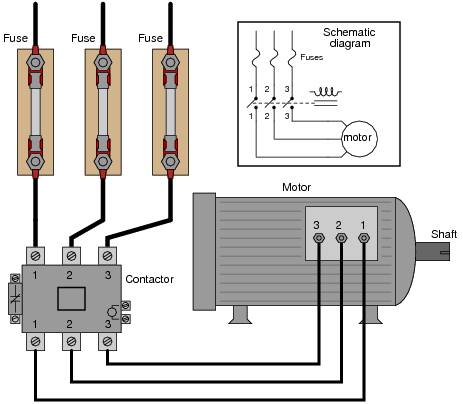 3 Phase Motors Wiring
 3 Phase Motor Wiring Explained
 How To Make 3 phase motor wiring diagram | 3 phase motor connection
 Electric Motor Wiring Diagram 3 Phase
 Three Phase Electric Motor Wiring
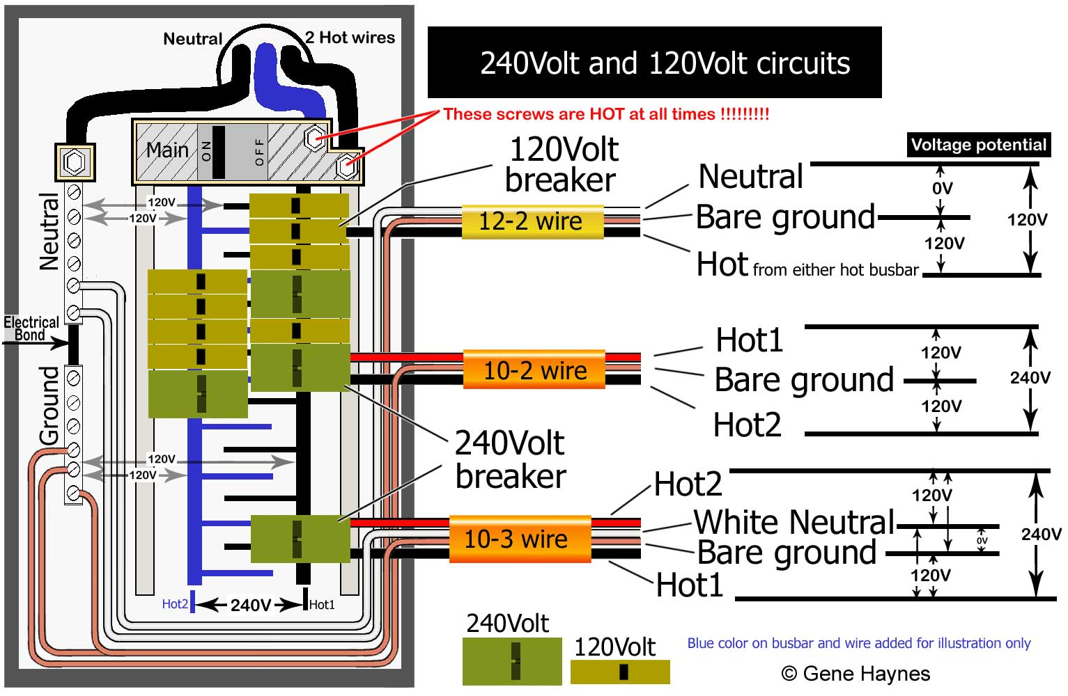 Wiring For A 240 Volt Circuit
 240v Wiring Basics
 Three Phase Motor Wiring Diagram Pdf
 Wiring 3 Phase Motor To Single Phase
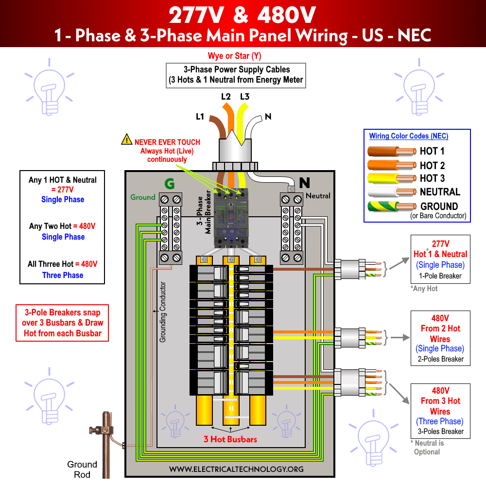 Three Phase Electrical Wiring Installation in Home - NEC & IEC
