Step-by-Step Guide Wiring Diagrams 120 Volt Single Phase Motors. Wiring diagrams essential understanding electrical connections a motor. this step-by-step guide, will walk through process wiring 120 volt single phase motor. you a beginner have experience electrical work, .
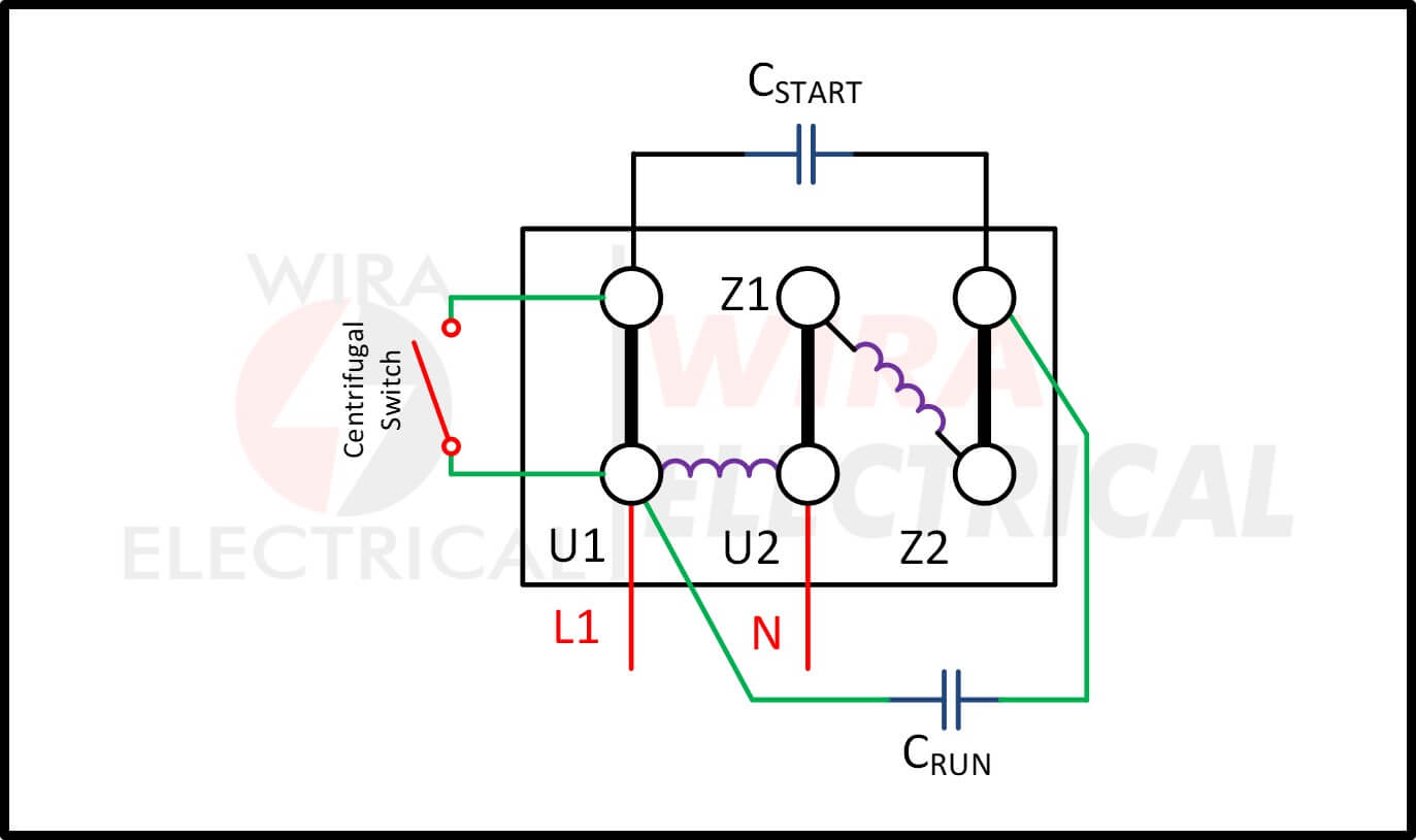 The wiring diagram a 120 volt single phase motor typically show connections the power supply, start winding, run winding, any additional components as capacitor. power supply usually two wires - line wire a neutral wire. line wire typically black the neutral wire typically white.
 Single Phase Electric Motor Wiring Diagrams, Terminal Connections, Frame Sizes, Electric Motor Information - Updated March 20, 2024 . 120 volts used. auxiliary starting winding displaced space the main winding 90 degrees. also a centrifugal switch starting capacitor. winding arrangement only .
 We learn single type single phase motor schematic single phase motors have schematic, connection, purpose. is learning type can find a good thing. Single Phase Motor Wiring Diagram. Single phase induction motor an AC motor operates supplied a single phase power.
 A 120 volt motor wiring diagram a schematic representation the electrical connections components in motor operating a 120 volt power supply. provides visual guide professionals technicians installing, troubleshooting, repairing motor. Understanding components a 120 volt motor wiring diagram .
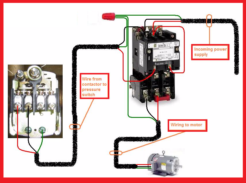 Learn to wire 120 volt motor a detailed wiring diagram. Understand different components connections required safe efficient operation. Step-by-step instructions illustrations for easy understanding.
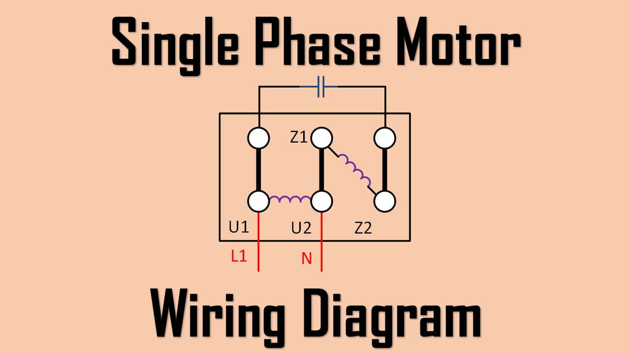 When comes wiring 120v motor, is important have clear understanding the components their functions. knowledge help ensure the motor wired correctly safely. Power supply: power supply the source electrical energy the motor. the case a 120v motor, typically from .
 Typical single phase motor wiring diagrams including HI/Lo voltage, start run capacitors (if used), start run windings centrifugal switches. Single phase motors generally a starter circuit get turning. starter circuit turned by centrifugal switch the motor reaches minimum RPM.
 Step-by-Step Guide Wiring Westinghouse Single Phase Motor. this step-by-step guide, will walk through process wiring Westinghouse single phase motor. wiring diagram the motor provide with the information, including correct connections wire colors. Step 1: Safety Precautions
 Another type single phase motor wiring diagram the capacitor-start motor. type motor a capacitor provide additional torque startup. wiring diagram a capacitor-start motor show the main winding, auxiliary winding, capacitor connected, well any necessary components as switches .
 Single Phase Motors Wiring Diagrams

 120 208v Single Phase Wiring Diagram
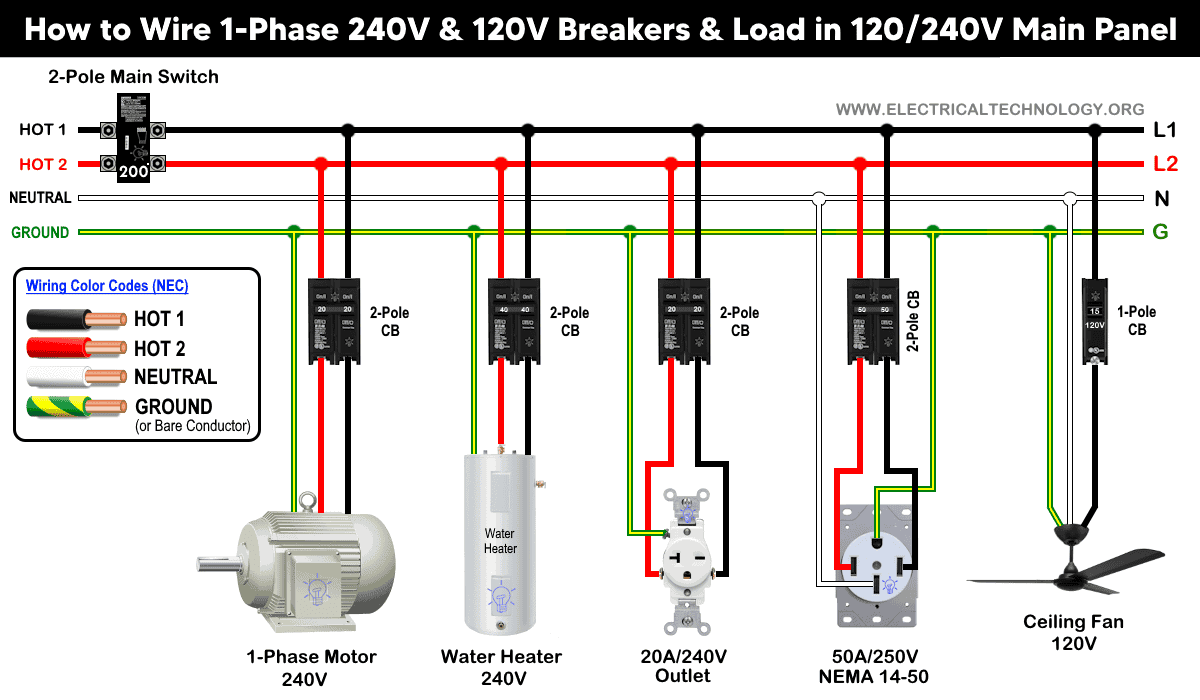 Single Phase Electrical Wiring Installation in Home - NEC & IEC
 Forward And Reverse Switch For Electric Motor
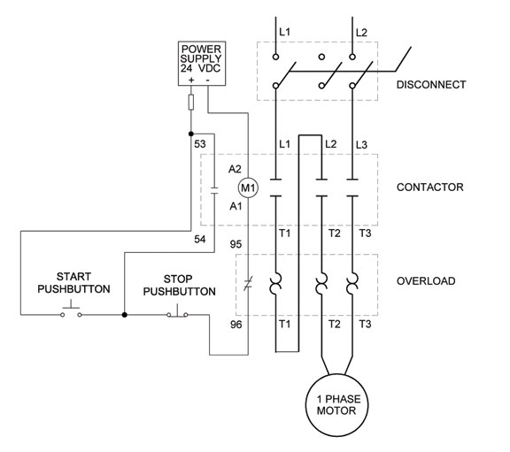 Single Phase 120v Motor Schematic
 Single Phase Motor Starter Circuit Diagram
 Motor Wiring Diagram Single Phase - Eneco
 A Complete Guide to Wiring Diagrams for 120 Volt Single Phase Motors
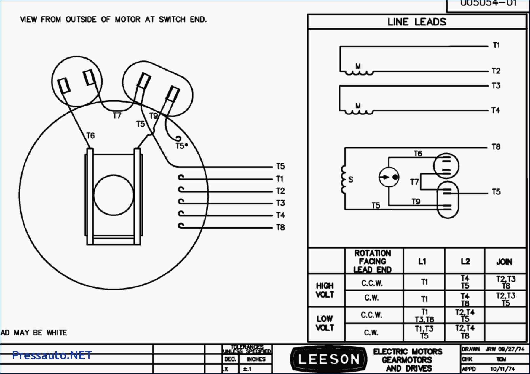 120v Single Phase Motor Wiring Diagrams
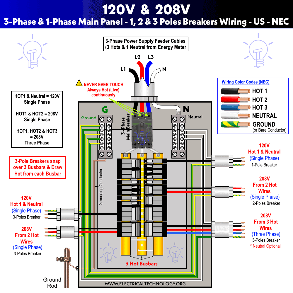 Circuit Diagram Of Single Phase Transformer
