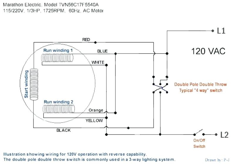
115 volt dc motor wiring. Thread starter . leads be separate it has constant 115 VDC applied the field the voltage the armature varied control speed. Bill . T. . Dayton 2 HP Electric Motor 115/230 Volts 3450 RPM Capacitor Start Single Phase AC Runs! Ookpik; Oct 24, 2022; Tooling, Parts .
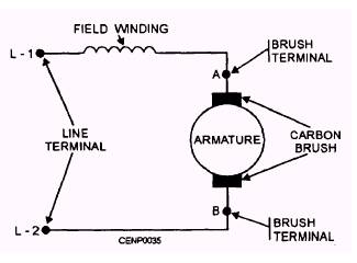 Page 1 C1XP02-115AC Instruction Guide Specifications Line Voltage 115 VAC, ±10%; single phase, 50/60 Hz Horsepower Range 1/20 - 1/8 Hp Armature Voltage Range 0 - 130 VDC Maximum Armature Current (continuous) 2 ADC Acceleration Time (no load) 1 Deceleration Time (no load) ; Page 2 Mounting MIN trimpot sets minimum speed.
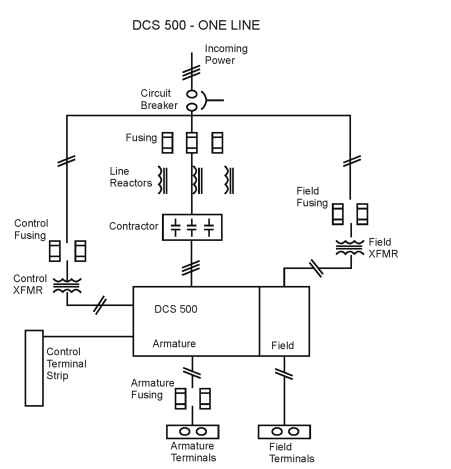 Figure 2-2 AC Line, Armature, Field*, Ground Connections Barrier Terminal Block Field Armature 115 208/230 Volts Ground (Earth) AC Line Input DC Motor Ground (Earth) AC Power Verify AC Line voltage matches control voltage rating, (115/208/230VAC - 50/60 Hz. 1phase). . Rated 24 Amps 115 and 208/230 Volts AC, single phase. Complies .
 Rated 24 Amps 115 and 208/230 Volts AC, single phase. Complies CE Directive RFI Filter BC24-LF 89/336/EEC (EN55022 and/or EN55011) relating the EMC Class Industrial Standard. * Factory installed the BC140-FBR model. . Page 26 Table 4-2 Armature and AC Line Fuse Chart Fuse Selection Approximate Motor Horsepower (AC Amps) Motor .
 Full Load Current Amps Single Phase AC Motors. find full load current your single phase motor running normal speed torque, your motor's horsepower rated motor voltage find full load current amps the chart below. . listed currents for system voltage ranges 110 ‑ 120 220 ‑ 240 .
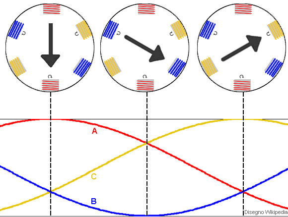
 Our single phase motors a permanent split capacitor design create torque the motor start load. 115 volt single phase motors often in applications industrial phase power isn't available. are capable operating either 50, 60 50-60 Hz, making ideal a variety applications.
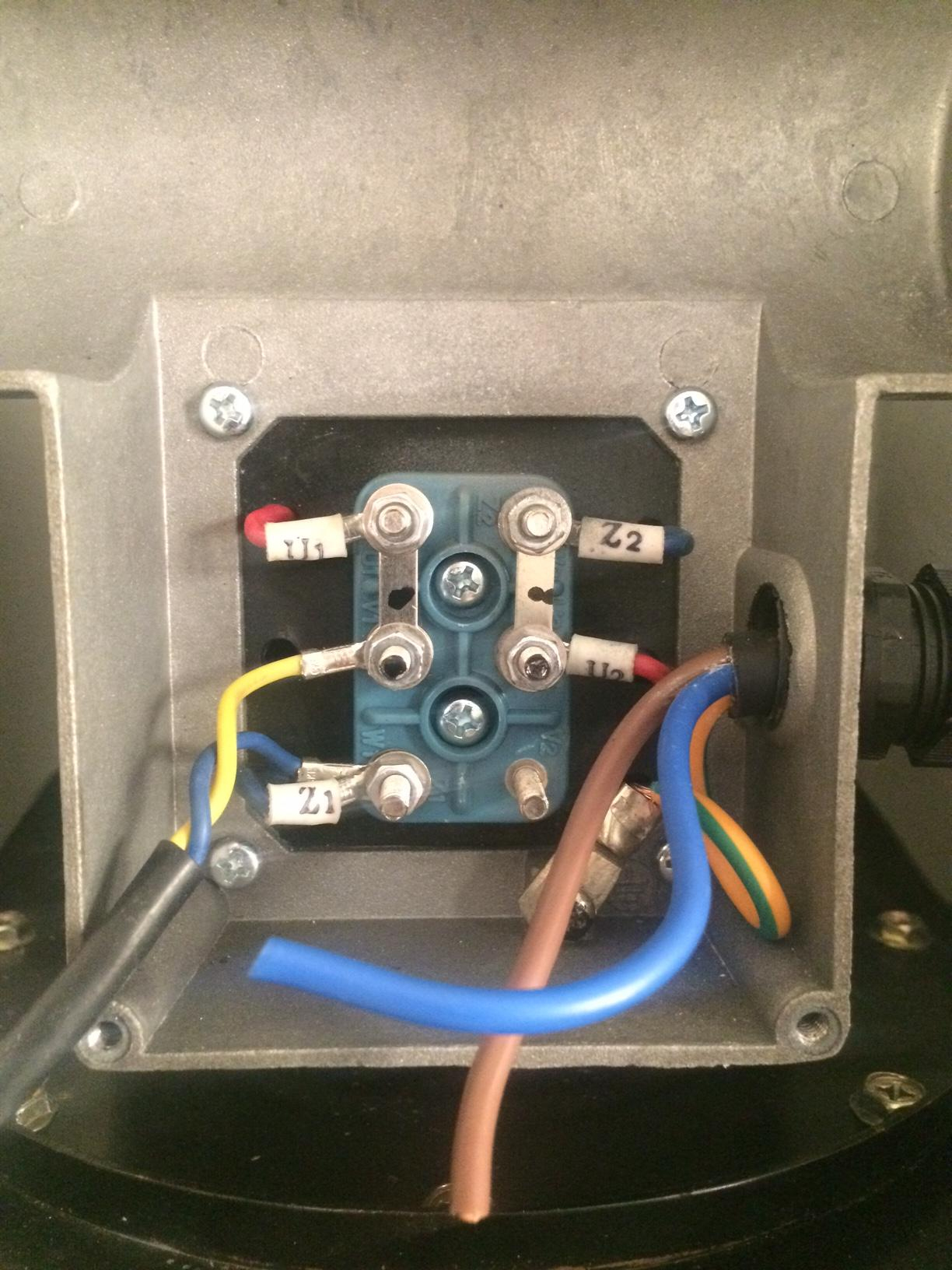
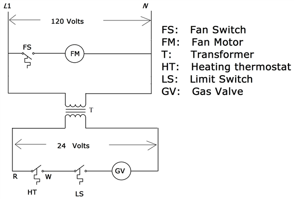 To complete single phase motor direction change, will to reverse polarity the starter winding. will the magnetic field change directions, the motor follow. . Home Hacks & Answers to Wire Red, White, Black Wires a 115-Volt AC Motor. Single Phase Motor Basics. the core an induction .
 1/4 2 Hp 115/230 VAC Single Phase 50/60 Hz. 3 Hp 230 VAC Single Phase 50/60 Hz. Applications: Constant torque, or replacement. Features: BC154, BCWD140 BC160 non-regen controls reversal means switching armature leads (BCWD140 a forward/brake/ reverse switch mounted).
 Variable-frequency drives 3-phase single-phase ac motors (80 pages) DC Drives Minarik MM20000A Series User Manual . AC Line Voltage 115 VAC, ±10%, 50/60 Hz, single phase Armature Voltage Range 0-130 VDC Form Factor (at base speed) . Figure 6). the simplest RUN/ BRAKE switch, a double pole, double throw switch rated at .
 for AC Motors "EI" designation coil electronic interface capability a PLC. Sprecher + Schuh Contactor Series Maximum Horsepower Single Phase Phase 115 Volt 230 Volt 200 Volt 230 Volt 460 Volt 575 Volt CA7-9 1/2 1 1/2 2 2 5 7-1/2 CA7-12 1/2 2 3 3 7-1/2 10 CA7-16 1 3 5 5 10 15 CA7-23 2 3 5 7-1/2 15 15 CA7-30 2 5 7-1/2 .

![[DIAGRAM] 115 Volt Ac Electric Motor Wiring Diagram - MYDIAGRAMONLINE [DIAGRAM] 115 Volt Ac Electric Motor Wiring Diagram - MYDIAGRAMONLINE](https://1.bp.blogspot.com/-1kNmEpPQyBw/UhdZ_0Kd6AI/AAAAAAAAGHQ/TQSx2KaNcNc/s1600/Ac-Motor-Wiring5.jpg) [DIAGRAM] 115 Volt Ac Electric Motor Wiring Diagram - MYDIAGRAMONLINE
[DIAGRAM] 115 Volt Ac Electric Motor Wiring Diagram - MYDIAGRAMONLINE
 1/3 HP 1725 RPM 115/230 Volt AC Motor | AC Motors Base Mount | AC
![[DIAGRAM] 115 Volt Ac Electric Motor Wiring Diagram - MYDIAGRAMONLINE [DIAGRAM] 115 Volt Ac Electric Motor Wiring Diagram - MYDIAGRAMONLINE](https://annawiringdiagram.com/wp-content/uploads/2019/02/115230-volt-electric-motor-wiring-diagram-wiring-diagram-century-ac-motor-wiring-diagram-115-230-volts.jpg) [DIAGRAM] 115 Volt Ac Electric Motor Wiring Diagram - MYDIAGRAMONLINE
[DIAGRAM] 115 Volt Ac Electric Motor Wiring Diagram - MYDIAGRAMONLINE
![[DIAGRAM] 115 Volt Ac Motor Wiring Diagram - MYDIAGRAMONLINE [DIAGRAM] 115 Volt Ac Motor Wiring Diagram - MYDIAGRAMONLINE](https://2020cadillac.com/wp-content/uploads/2019/02/115-volt-ac-motor-wiring-wiring-diagrams-thumbs-baldor-motor-wiring-diagram-1024x683.jpg) [DIAGRAM] 115 Volt Ac Motor Wiring Diagram - MYDIAGRAMONLINE
[DIAGRAM] 115 Volt Ac Motor Wiring Diagram - MYDIAGRAMONLINE
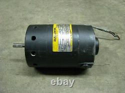 Baldor Industrial Electric Motor 10,000 Rpm 1/2 Hp 115 Volt Ac 1 Phase
 115v Ac Electric Motor Wiring Graphic
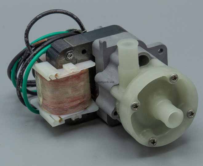 March 0115-0064-0110 Mag-Drive Centrifugal Pump - 115 Volts AC Single
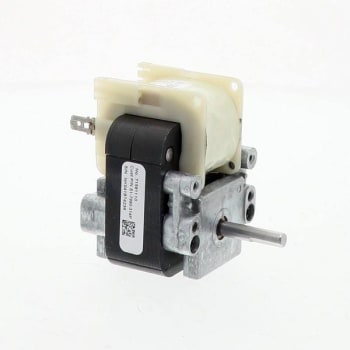 York Motor Inducer 115 Volt Ac Single Phase 2900 RPM 1 Spd Ccw Lead End
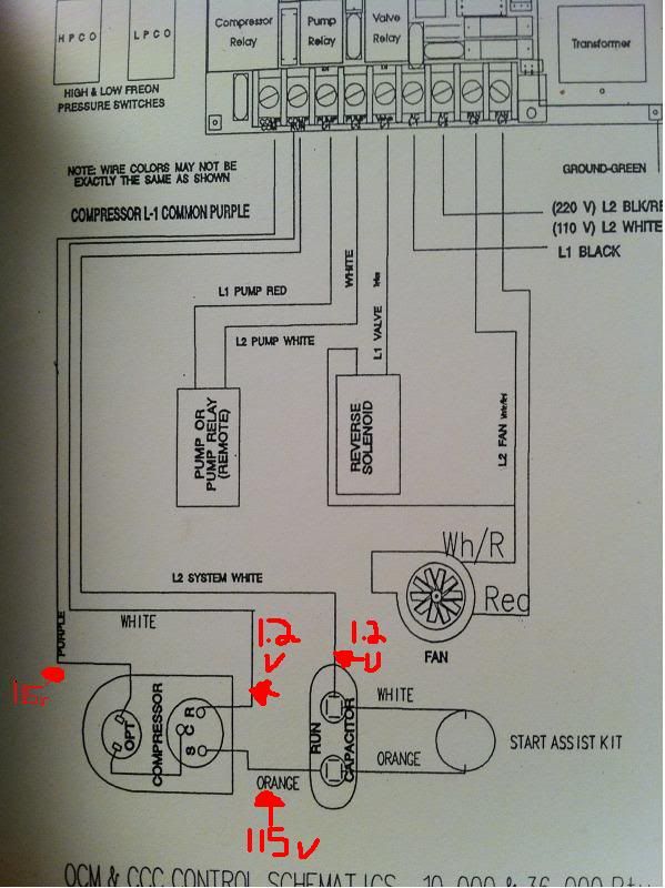 115v Ac Electric Motor Wiring Graphic
![[Solved] a) A 115-volt shunt motor has an armature whose resistance is [Solved] a) A 115-volt shunt motor has an armature whose resistance is](/img/placeholder.svg)
