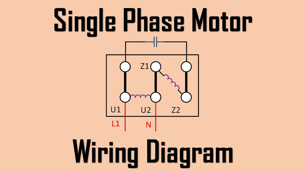
Permanent Split Phase Capacitor Motor Wiring Diagram. as name implies, single phase motor diagram work a split phase generated a capacitor. capacitance the capacitor the reactance the winding shift phase some extent. is permanent capacitor single phase motor wiring diagram.
 SINGLE PHASE MOTOR WIRING DIAGRAMS Single Voltage Motor 208-230V CCW CW L2 L1 T1 T8 T4 T5 T1 T5 T4 T8 Dual Voltage Motor 115V 208-230V 208-230V 460V Voltage High Voltage . Microsoft Word - Single Phase Author: dbostian Created Date: 8/4/2011 11:42:53 .
 Here a website explains operation different types electric motors single-phase electric motor diagrams. links wiring diagrams bathroom fans, ceiling fans, switched outlets, 2-way, 3-way, 4-way switches, telephones be here.
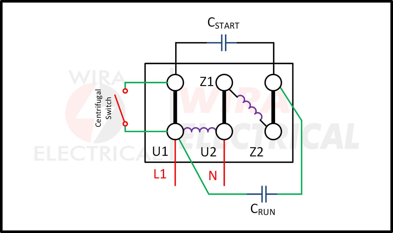
 A single phase motor wiring diagram a visual representation the motor's electrical connections. shows the components terminals the motor connected, allowing electrical engineers technicians properly install troubleshoot motor. understanding wiring diagram, can determine .
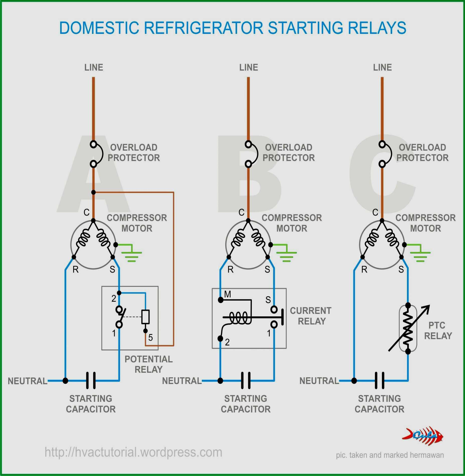
 Typical single phase motor wiring diagrams including HI/Lo voltage, start run capacitors (if used), start run windings centrifugal switches. Single phase motors generally a starter circuit get turning. starter circuit turned by centrifugal switch the motor reaches minimum RPM.

 Step-by-Step Guide Wiring Diagrams 120 Volt Single Phase Motors. Wiring diagrams essential understanding electrical connections a motor. this step-by-step guide, will walk through process wiring 120 volt single phase motor. you a beginner have experience electrical work, .
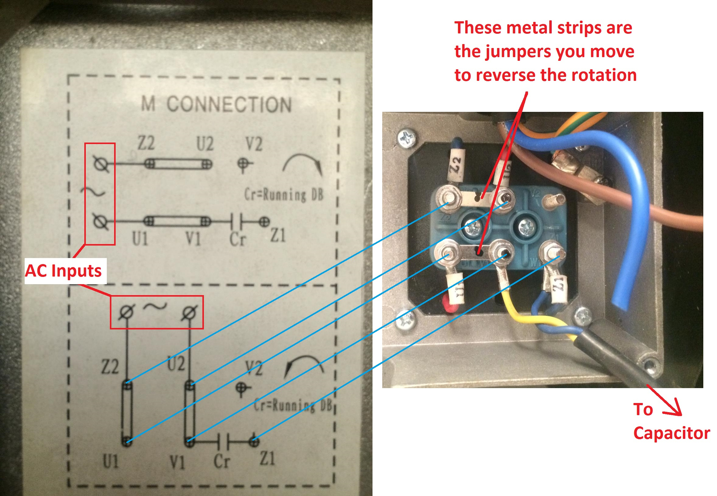 In summary, wiring diagrams single phase motors play vital role understanding electrical connections components involved operating motors. following diagrams correctly, individuals ensure proper functioning their single phase motors troubleshoot potential issues effectively.
 Single-phase motor connection wiring diagrams provide visual representation how motor be connected the power supply other components. diagrams typically show main components the motor, as stator, rotor, various terminals. terminal a specific purpose must connected correctly .
 The wiring diagram a 120 volt single phase motor typically show connections the power supply, start winding, run winding, any additional components as capacitor. power supply usually two wires - line wire a neutral wire. line wire typically black the neutral wire typically white.
 Motor Wiring Diagram Single Phase - Eneco
 Single Phase Motor Wiring Diagram | EdrawMax | EdrawMax Templates
 Single Phase Motor Wiring Diagram and Examples | Wira Electrical
 Single Phase Motor Wiring Diagrams 120 Volt
 How To Make Single phase Motor Wiring With Contactor Diagram | Motor
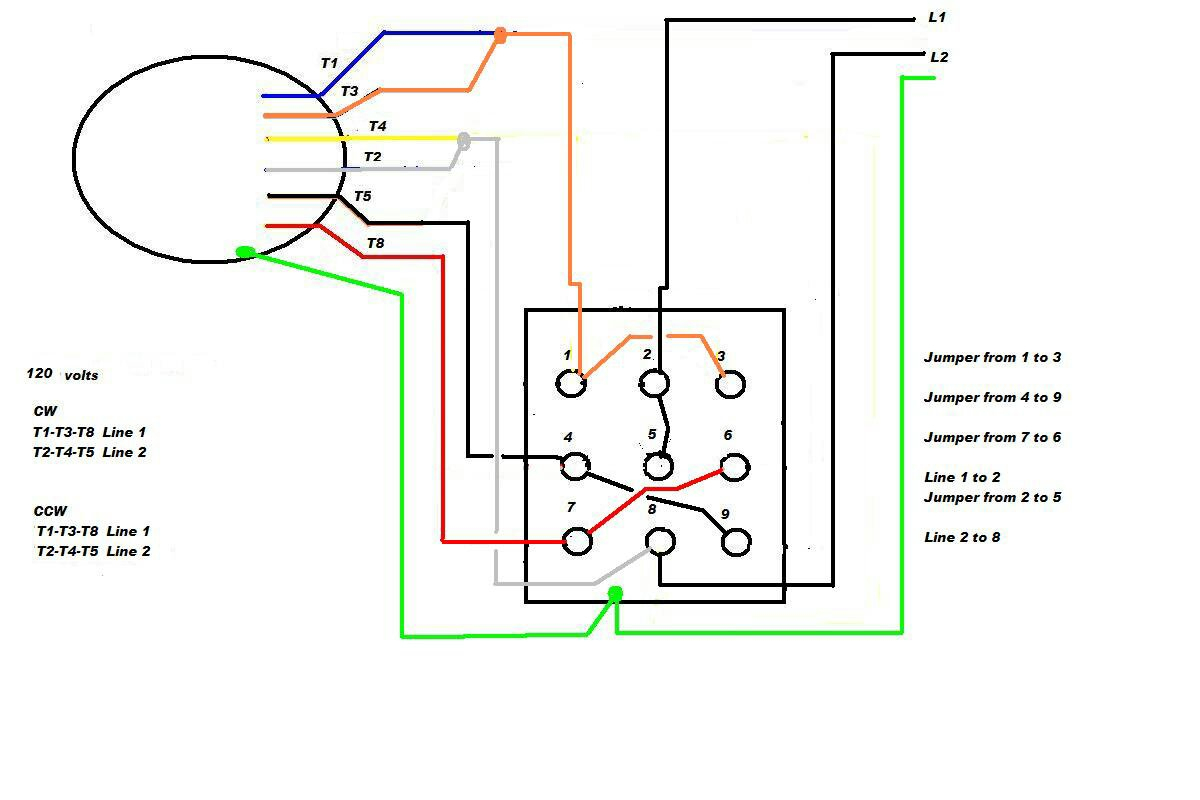 Electric Motor Wiring Diagram Single Phase
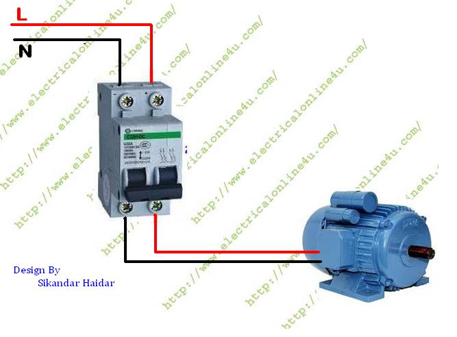 How to wire Single Phase Motor From Two Pole Circuit Breaker
 Single Phase Motor Wiring Diagram and Examples | Wira Electrical
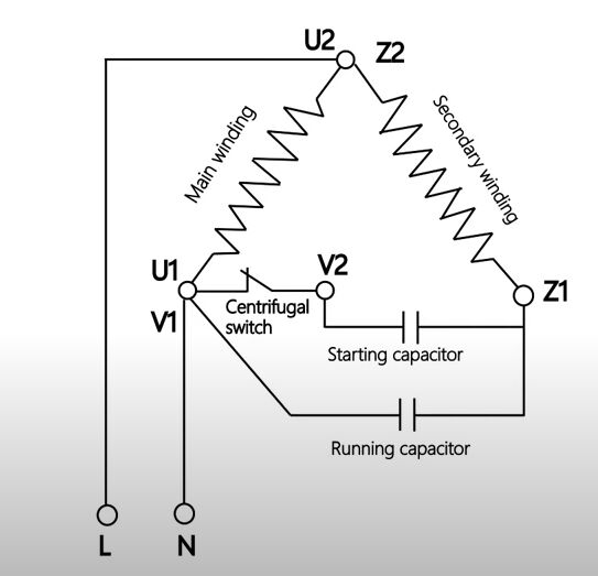 How to Wire Single Phase Motor? | ATOcom
 How To Make Single Phase Electric Motor Connection | Single Phase Motor
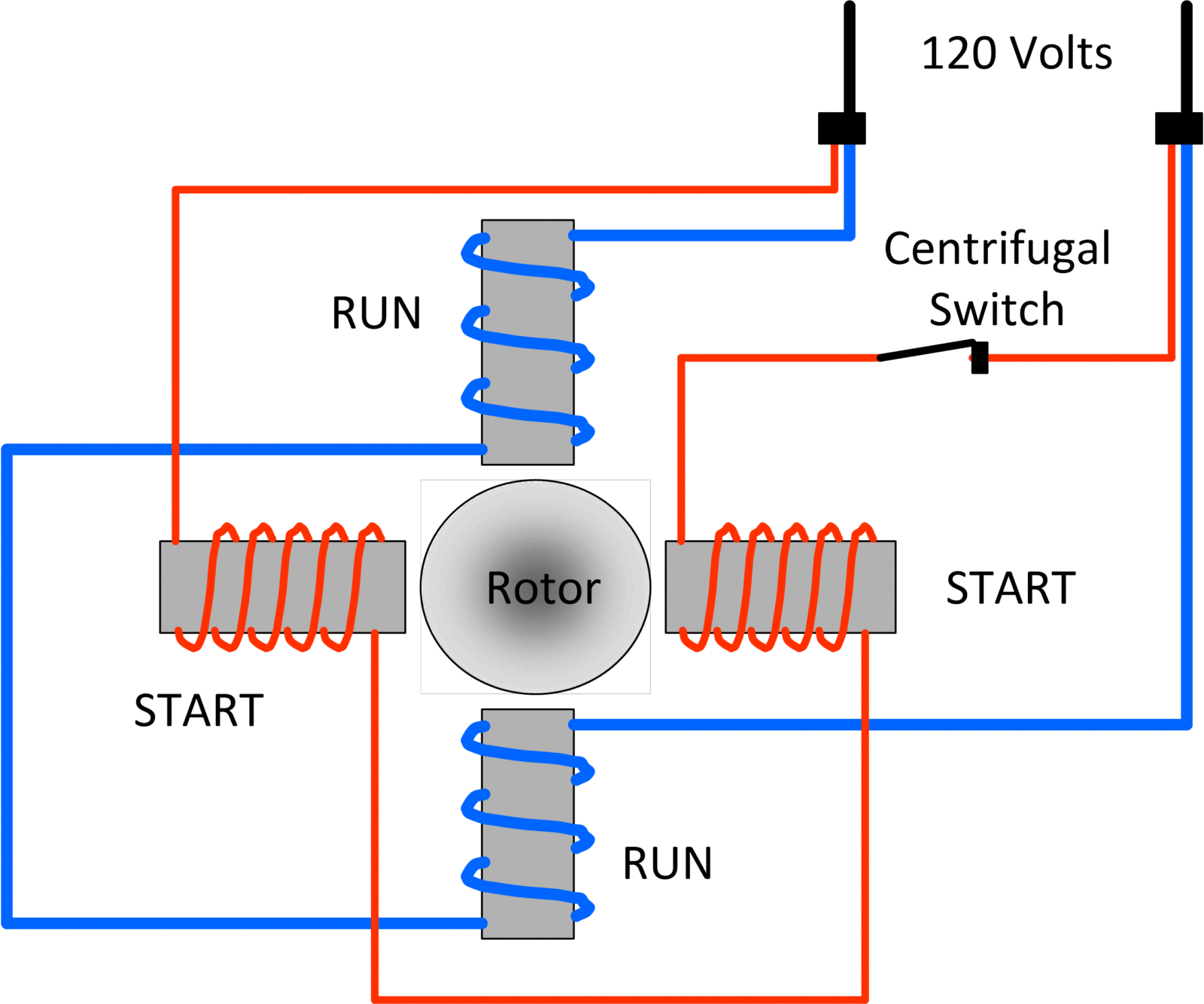 Types of Single Phase Induction Motors | Single Phase Induction Motor
